- 您现在的位置:买卖IC网 > Sheet目录311 > AS5140 PB (ams)BOARD PROGRAM AS5140
�� �
�
�AS5140H�
�Data� Sheet� -� D� e� t� a� i� l� e� d� D� e� s� c� r� i� p� t� i� o� n�
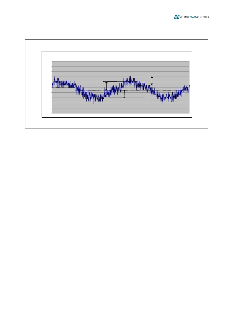
�Figure� 23.� Example� of� Linearity� Error� Over� 360o�
�0.5�
�0.4�
�0.3�
�0.2�
�0.1�
�0�
�Err� max�
�transition� noise�
�-0.1�
�1�
�55�
�109�
�163�
�217�
�271�
�325�
�379�
�433�
�487�
�541�
�595�
�Err� min�
�649�
�703�
�757�
�811�
�865�
�919�
�973�
�outputs.� It� is� specified� as� 0.06� degrees� rms� (1� sigma)� .� This� is� the� repeatability� of� an� indicated� angle� at� a� given� mechanical� position.� The�
�-0.2�
�-0.3�
�-0.4�
�-0.5�
�7.12.2� Transition� Noise�
�Transition� noise� is� defined� as� the� jitter� in� the� transition� between� two� steps.� Due� to� the� nature� of� the� measurement� principle� (Hall� sensors� +�
�Preamplifier� +� ADC),� there� is� always� a� certain� degree� of� noise� involved.� This� transition� noise� voltage� results� in� an� angular� transition� noise� at� the�
�1�
�transition� noise� has� different� implications� on� the� type� of� output� that� is� used:�
�Absolute� Output;� SSI� Interface:� The� transition� noise� of� the� absolute� output� can� be� reduced� by� the� user� by� applying� an� averaging� of� read-�
�ings.� An� averaging� of� 4� readings� will� reduce� the� transition� noise� by� 50%� =� 0.03o� rms� (1� sigma).�
�PWM� Interface:� If� the� PWM� interface� is� used� as� an� analog� output� by� adding� a� low� pass� filter,� the� transition� noise� can� be� reduced� by� lower-�
�ing� the� cutoff� frequency� of� the� filter.� If� the� PWM� interface� is� used� as� a� digital� interface� with� a� counter� at� the� receiving� side,� the� transition�
�noise� may� again� be� reduced� by� averaging� of� readings.�
�Incremental� Mode:� In� incremental� mode,� the� transition� noise� influences� the� period,� width� and� phase� shift� of� the� output� signals� A,� B� and�
�Index.� However,� the� algorithm� used� to� generate� the� incremental� outputs� guarantees� no� missing� or� additional� pulses� even� at� high� speeds� (up�
�to� 10.000� rpm� and� higher).�
�7.12.3� High� Speed� Operation�
�The� AS5140H� samples� the� angular� value� at� a� rate� of� 10.42k� samples� per� second.� Consequently,� the� incremental� and� the� absolute� outputs� are�
�updated� each� by� 96μs.� At� a� stationary� position� of� the� magnet,� this� sampling� rate� creates� no� additional� error.�
�Absolute� Mode.� With� the� given� sampling� rate� of� 10.4� kHz,� the� number� of� samples� (n)� per� turn� for� a� magnet� rotating� at� high� speed� can� be�
�calculated� by:�
�n� =� ---------------------------�
�60�
�rpm� ?� 96� μ� s�
�(EQ� 6)�
�In� practice,� there� is� no� upper� speed� limit.� The� only� restriction� is� that� there� will� be� fewer� samples� per� revolution� as� the� speed� increases.�
�Regardless� of� the� rotational� speed,� the� absolute� angular� value� is� always� sampled� at� the� highest� resolution� of� 10� bit.� Likewise,� for� a� given� number�
�of� samples� per� revolution� (n),� the� maximum� speed� can� be� calculated� by:�
�rpm� =� --------------------�
�60�
�n� ?� 96� μ� s�
�1.� Statistically,� 1� sigma� represents� 68.27%� of� readings;� 3� sigma� represents� 99.73%� of� readings.�
�(EQ� 7)�
�www.austriamicrosystems.com/AS5140H�
�Revision� 1.4�
�29� -� 37�
�发布紧急采购,3分钟左右您将得到回复。
相关PDF资料
ASDMB-ADAPTER-KIT
ASDMB MEMSPEED P II OSC KIT
ASFLMPLP-ADAPTER-KIT
ASFLMPLP MEMSPEED P II OSC KIT
AT24C01-10SI-1.8
IC EEPROM 1KBIT 400KHZ 8SOIC
AT24C01B-TSU-T
IC EEPROM 1KBIT 1MHZ SOT23-5
AT24C02C-XHM-B
IC EEPROM 2KBIT 1MHZ 8TSSOP
AT24C04AN-10SI-2.7
IC EEPROM 4KBIT 400KHZ 8SOIC
AT24C08B-PU
IC EEPROM 8KBIT 1MHZ 8DIP
AT24C1024B-TH25-B
IC EEPROM 1MBIT 1MHZ 8TSSOP
相关代理商/技术参数
AS51400FLF
制造商:TT Electronics / IRC 功能描述:AS51400FLF
AS51400HLF
制造商:TT Electronics / IRC 功能描述:AS51400HLF
AS51400JLF
制造商:TT Electronics / IRC 功能描述:AS51400JLF
AS51401FLF
制造商:TT Electronics / IRC 功能描述:AS51401FLF
AS51401HLF
制造商:TT Electronics / IRC 功能描述:AS51401HLF
AS51401JLF
制造商:TT Electronics / IRC 功能描述:AS51401JLF
AS51402FLF
制造商:TT Electronics / IRC 功能描述:AS51402FLF
AS51402HLF
制造商:TT Electronics / IRC 功能描述:AS51402HLF